3x3 Interface board
<<Previous | TOC | Next>>
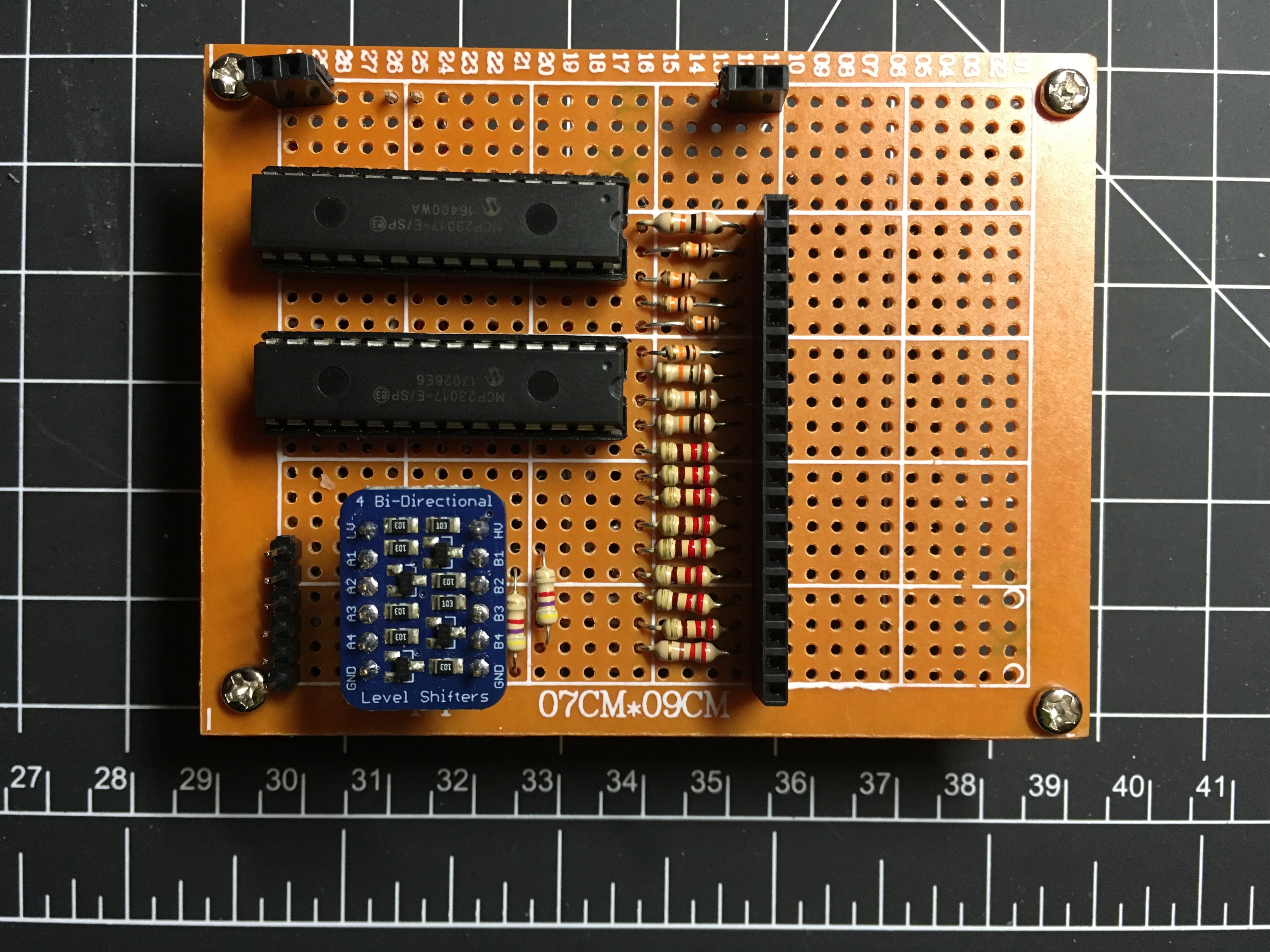
I transferred my breadboard circuit to a protoboard. I'm now calling it my 3x3 interface board. This board is for pairing up my RPi with my 3x3 chess board that I mention in previous posts. Assembly went fairly well, although I wired up my pull-up resistors wrong. I thought i was going to have to mess with desoldering and pulling them out of the board but I was able to reroute the wires instead.
3x3 Interface board
I was not getting reliable 3.3V power to power the MCP chips and LEDs from the RPi. I decided to run the interface board at 5V, since that is what will be coming from the power supply. I can either tap the power supply, or run off the 5V pin on the RPi. I still need to test a little more, but I think running off the pin should be fine. For now though I have a second power supply to power the interface board.
But as a result of using 5V, I need to convert the 5V i2c signal from the MCP23017 chips to 3.3V for the RPi. It only accepts 3.3V input. To convert it, I am using a level shifter. This happily converts i2c signals from 5V to 3.3V and visa versa.
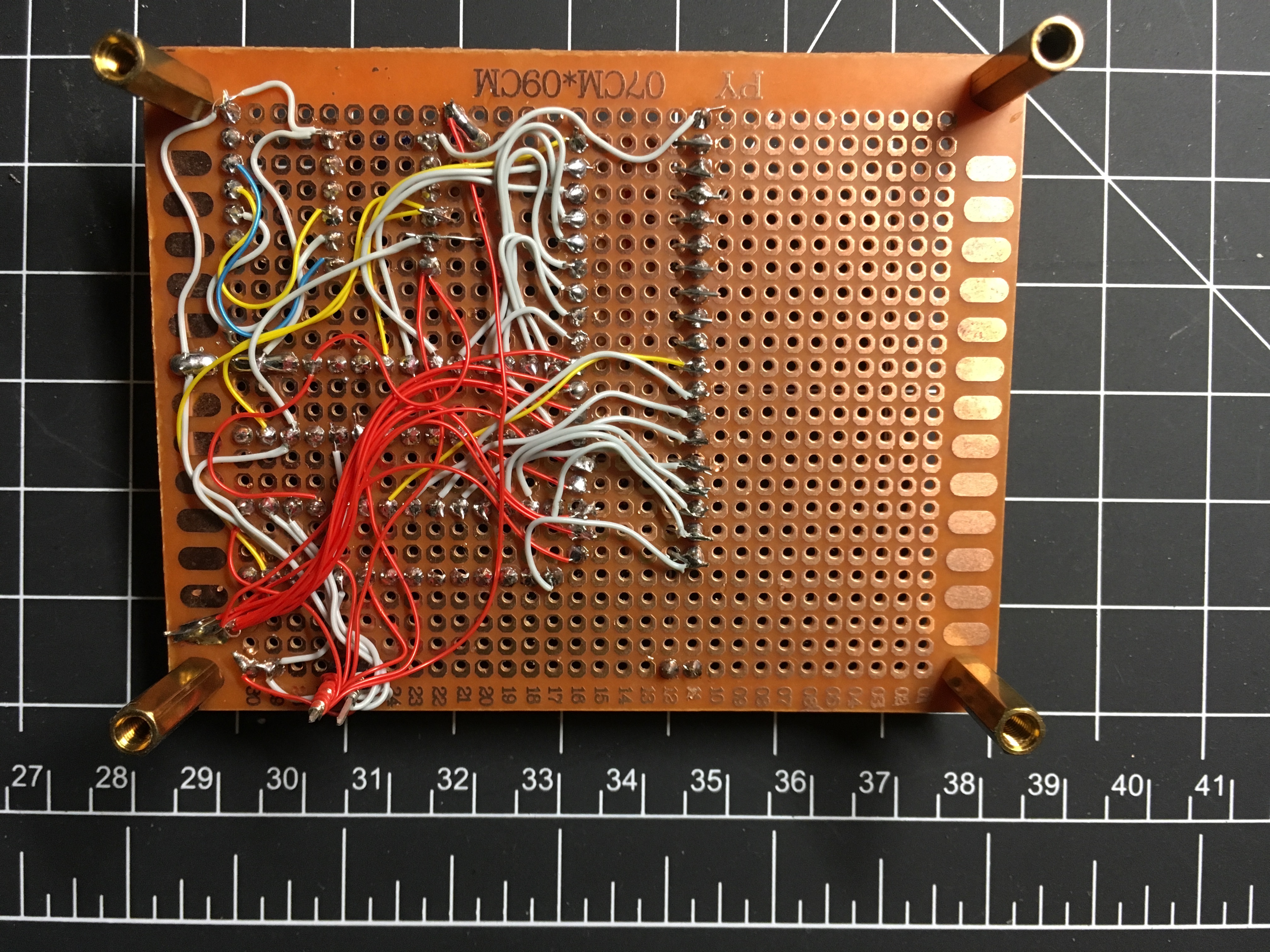
The underside shown below taught me a couple things.
Underside
One is that I needed to space things out a little more to make getting at pins easier. I'd rather take up a little extra space then to take way longer to wire things up and struggle soldering in a cramped area. And this is exactly what I did for my first interface board for my 8x8, which I'll post about shortly.
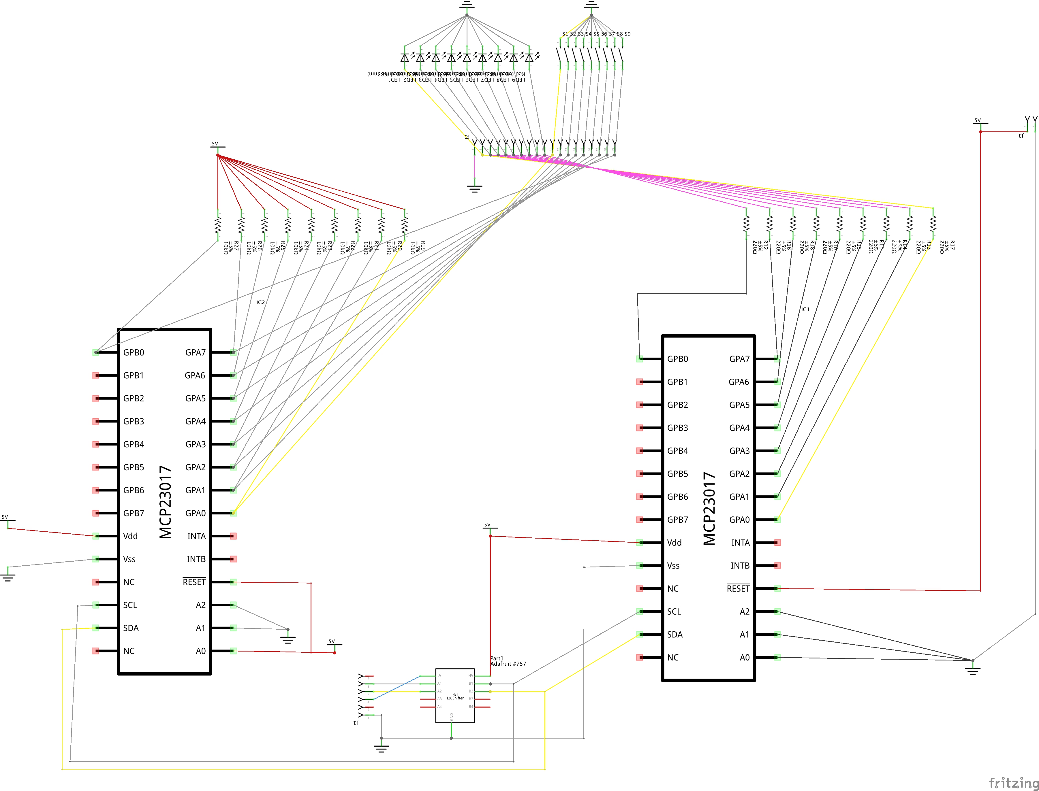
The schematic is shown below. Fritzing schematic is mcp-3x3.fzz.
Schematic


