Nut Box
<<Previous | TOC | Next>>
I had mounted the legs to the top panel using a hot glue gun, which I had always planned to do. I don't plan to takes the legs off once mounted. But since the reed switches I had been using proved to be unreliable and I wasn't sure how the new batch from DigiKey would hold up, I realized I didn't want to glue the bottom panel. I needed to be able to get into the e-board if I needed to change out a reed switch. Besides, how would I show off the design to anyone if I couldn't open the back up? So gluing the bottom on was out. Ideally I would be able to just unscrew it.
Since the feet were printed from PLA, drilling was easy enough. But the inside of a 3D printed part is actually hollow with a honey comb pattern. So there isn't a lot of strength. Putting a self tapping or wood screw in once or twice might work, but after that, the hole would be too messed up and stripped out.
After a little googling, I found an excellent site that talked about adding screw threads to printed parts. Three options it mentioned sounded very interesting.
The first interesting one was that you could just print the model with a hole designed right into it, and screw into the hole. The PLA is plenty strong enough to handle it a self tapping or a machine screw. You could even tap it with a tapping tool first, to make the screw go into easier. However, as PLA is just plastic, it would eventually strip out after repeated use. It would however be stronger and last longer then drilling into the part.
Second was using a brass insert, which I found very interesting. I would like to try it on a future project. However, as I would have to order the inserts and I didn't know the thread pitch of my existing screws, I didn't want to go this route.
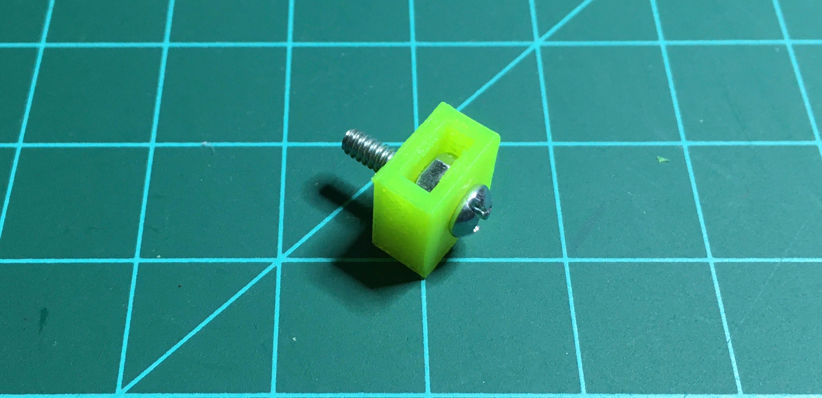
Testing the size of the pocket
The option I went with, was creating a pocket for a nut. You design the pocket into your model, then press fit a nut into it. It creates a durable metal-on-metal contact for the screw that will not strip out.
Note: The site mentions designing a hexagonal pocket. I found it worked better if you designed a square that the nut fits into instead. Using a square allows for a little extra room for strands or burrs that may have gotten into the pocket during printing. I found a hex pocket always ended up too tight, or just barely fitting, but the square was perfect. The sides of the square are plenty strong to keep the nut from turning.
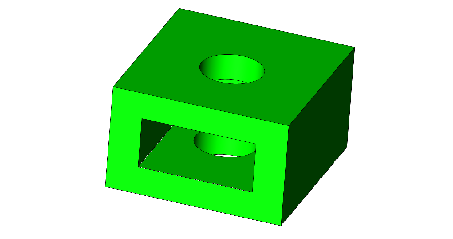
I first designed a tiny box with a pocket and hole, as shown below. The actual prints are typically a little smaller, or larger then your model, so it took a few prints to get it right.
Note: Keep your test prints as small as possible. If you print a few different sizes at the same time, careful not to mix them up! Not that I would ever do such a thing ;-)
Another issue you might run into are little burrs. When creating a pocket in a 3D print that doesn't have supports (also called an overhang), you will typically get strands that hang down into the cavity. In my case, I was able to control that by changing the orientation of the model. Instead of printing it horizontally, I printed it vertically. As that isn't always an option, note that for such a small cavity the printer is more then capable of printing your part without an issue. In fact, I'm not sure if it was because of the overhang, or because it was small and the hex design I first tried caused some strands. For my prints, I measured the nut and added 0.25mm to the measurement. The height I added 0.4mm.
3D model of the nut box
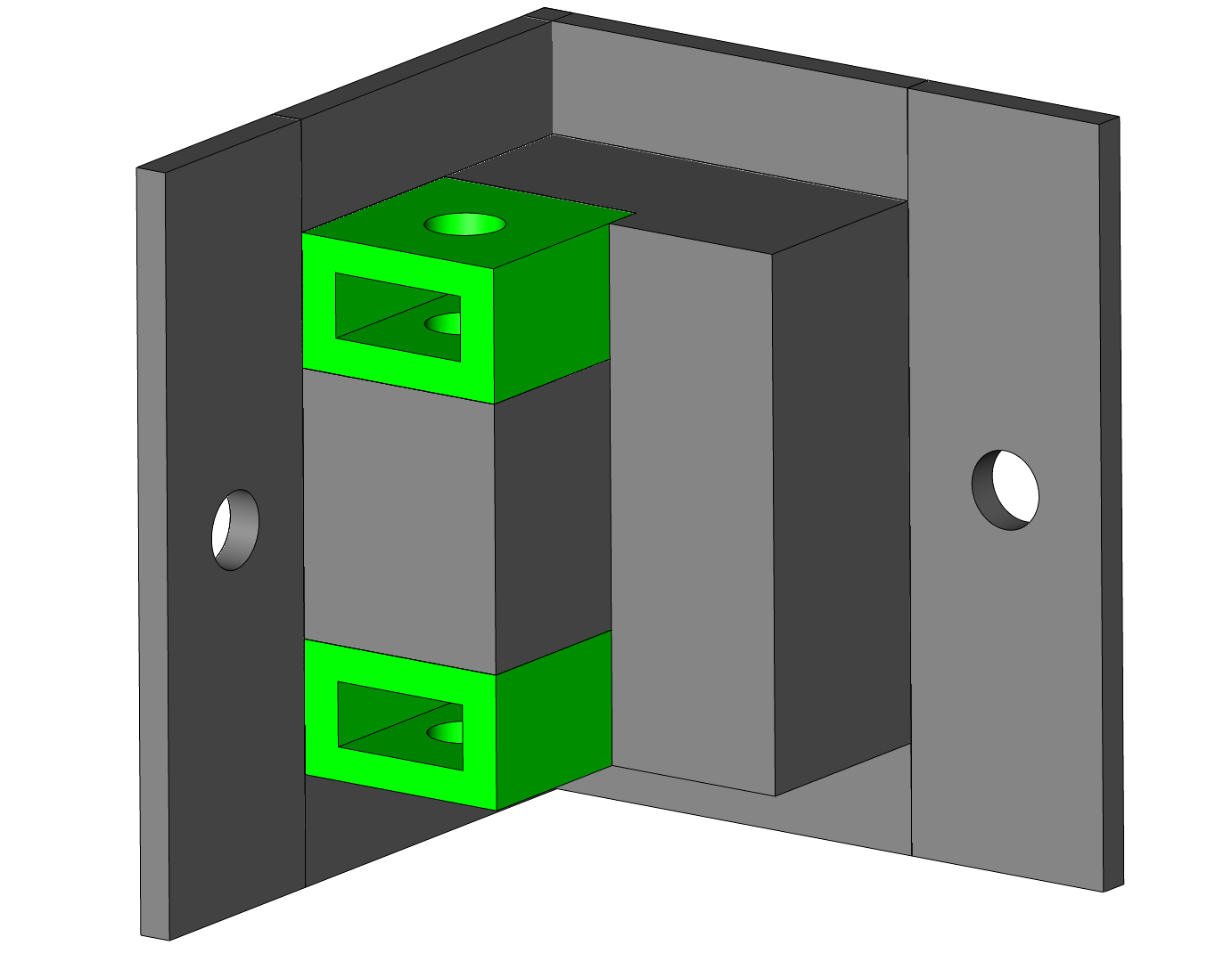
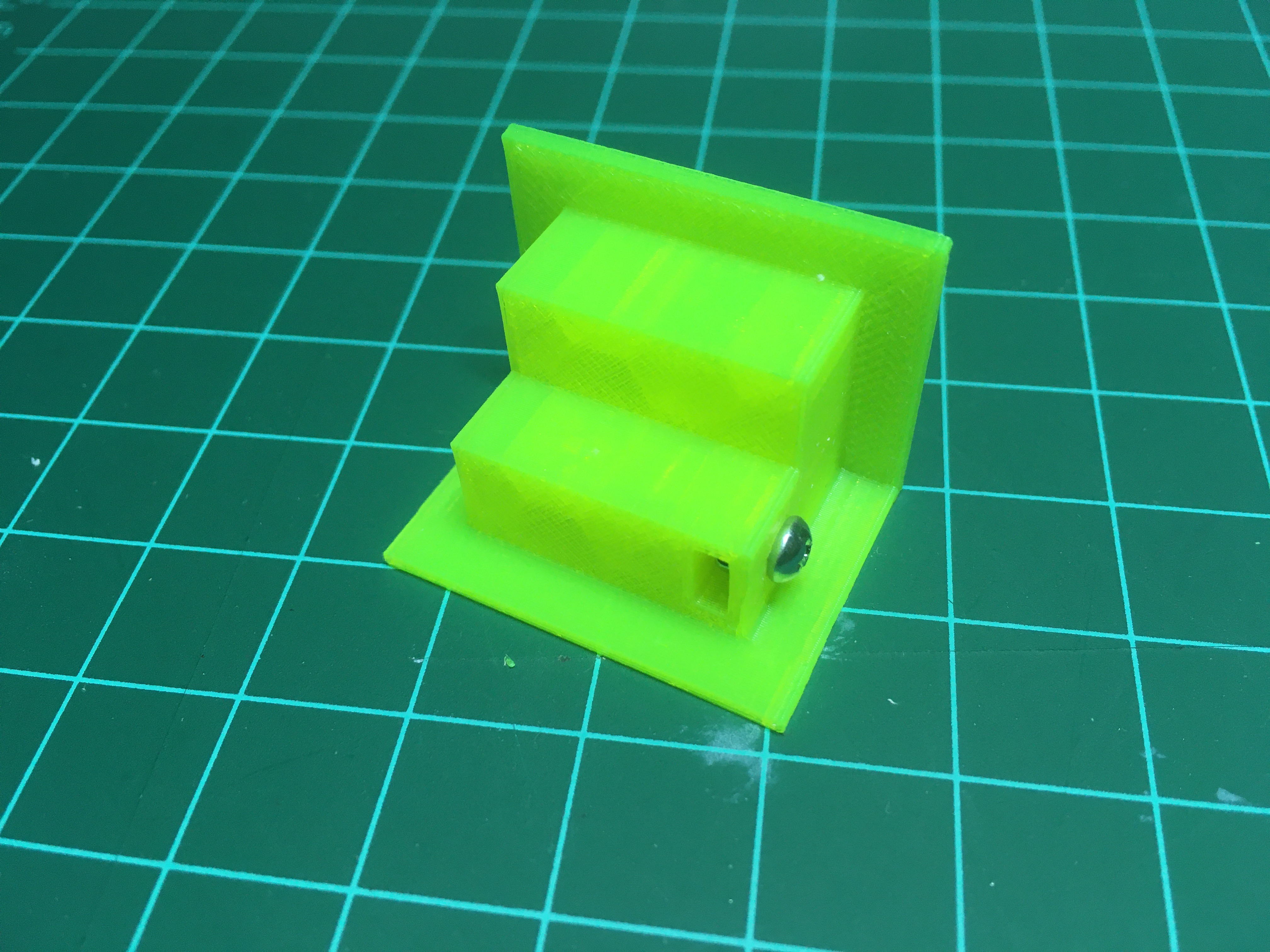
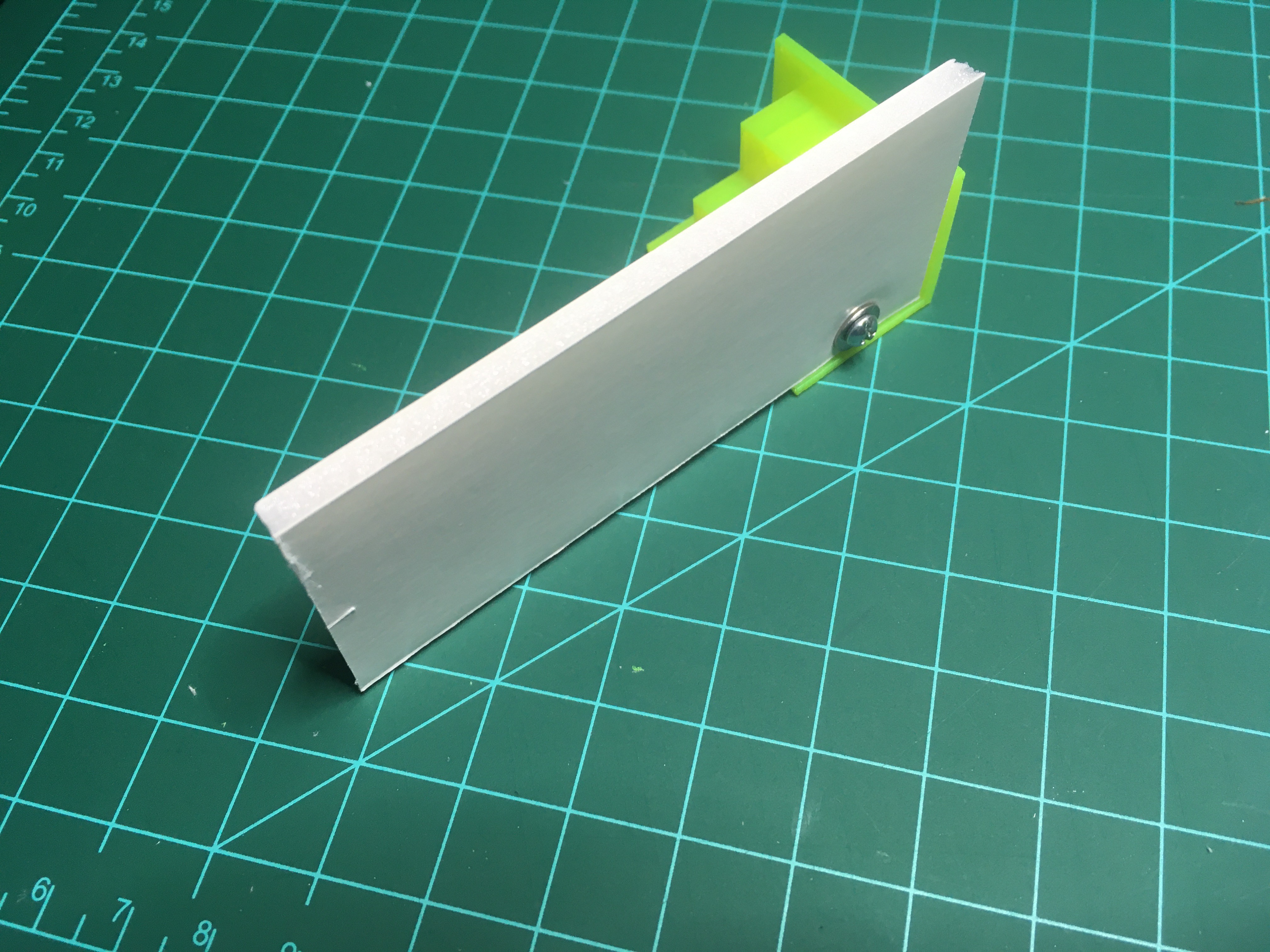
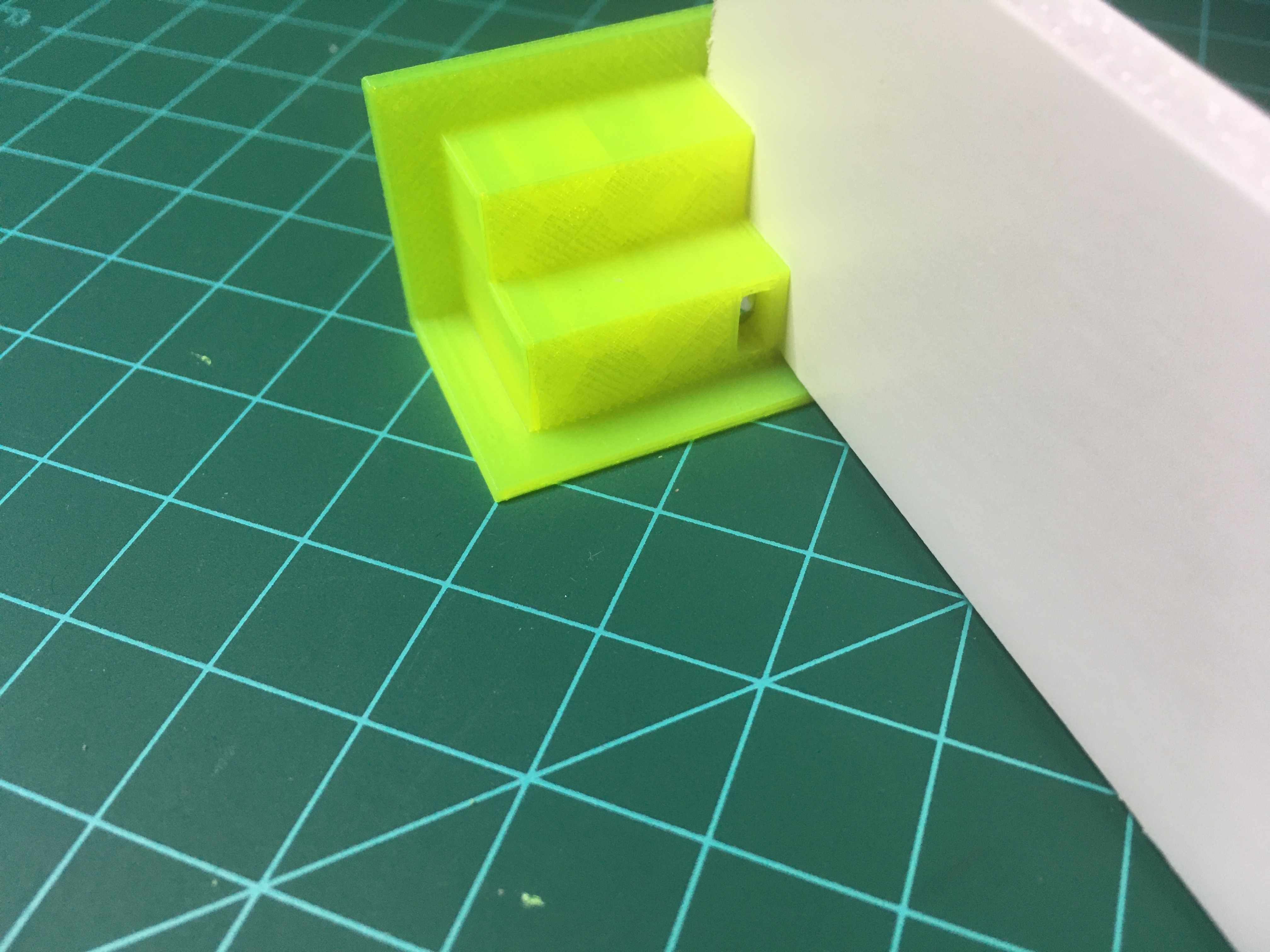
Once I had a model that worked, I inserted it into my leg model, and did a test print, shown below. I also show a 5mm foam board mounted to the leg. It is the same board that I use as my e-board's bottom panel.
Model with nut box
Print with nut box and nut press fitted in, and screw inserted
