ChessLR Tour
Date: 2020-04-07 22:22:04
<<Previous | TOC | Next>>
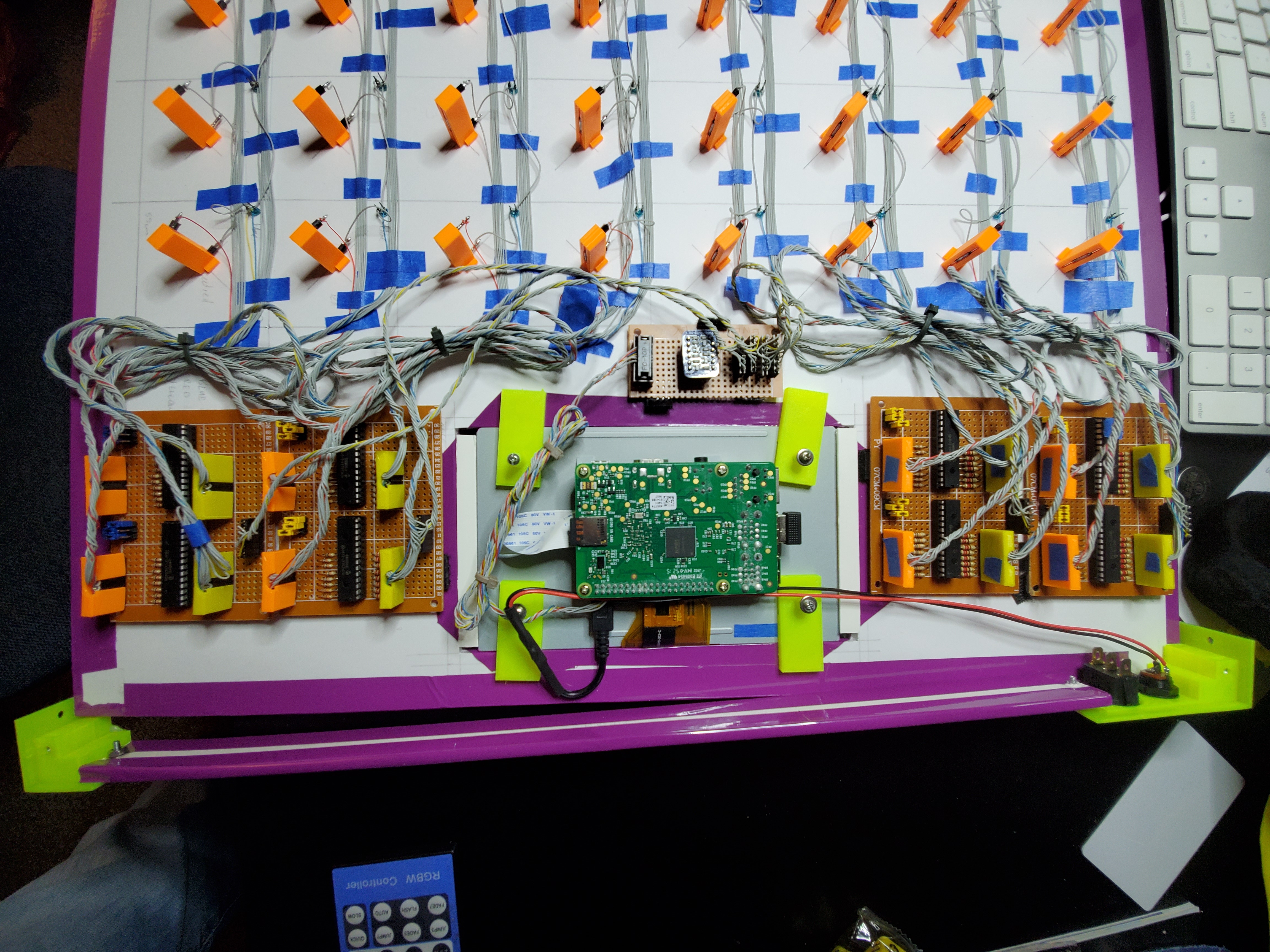
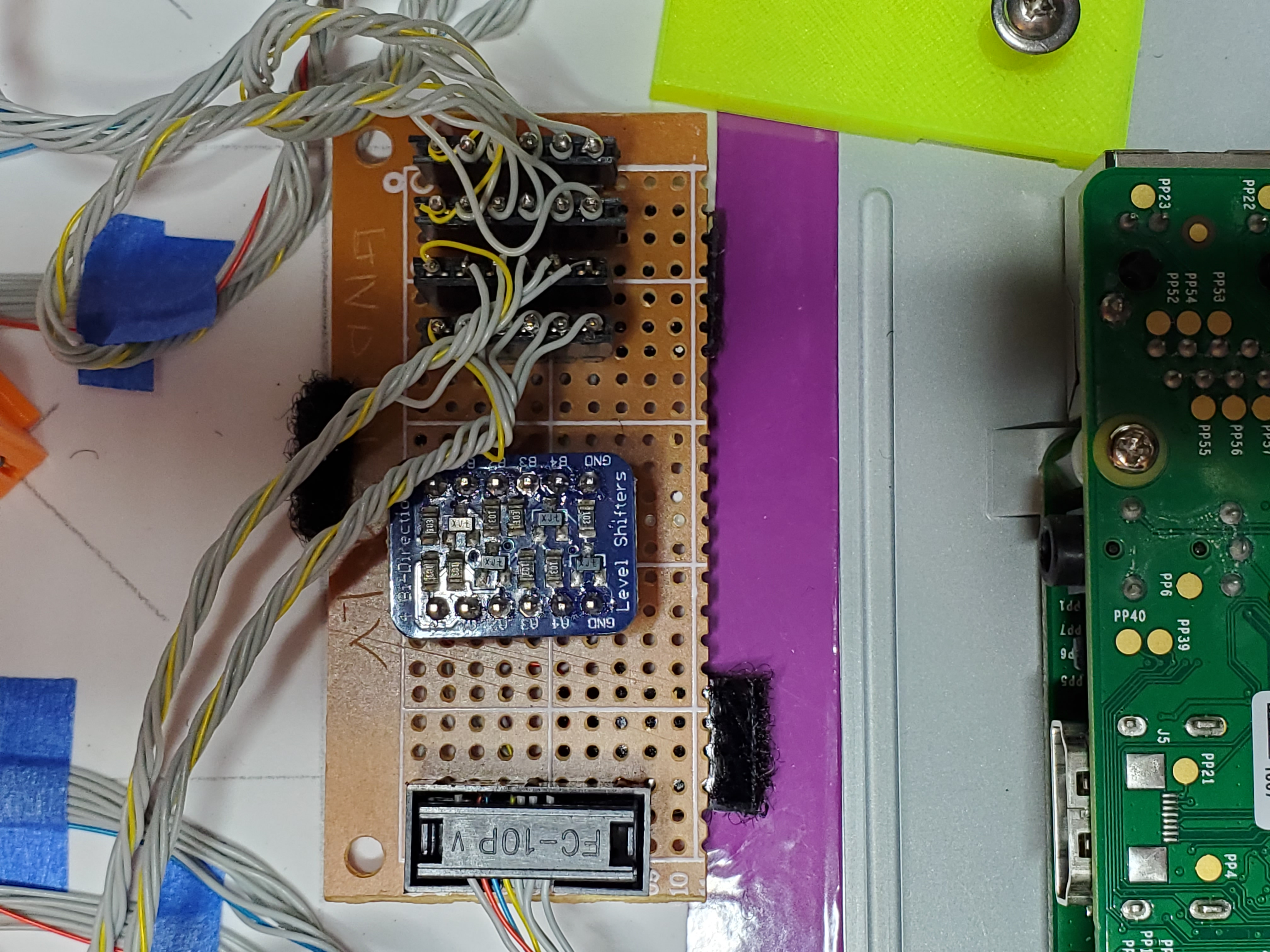
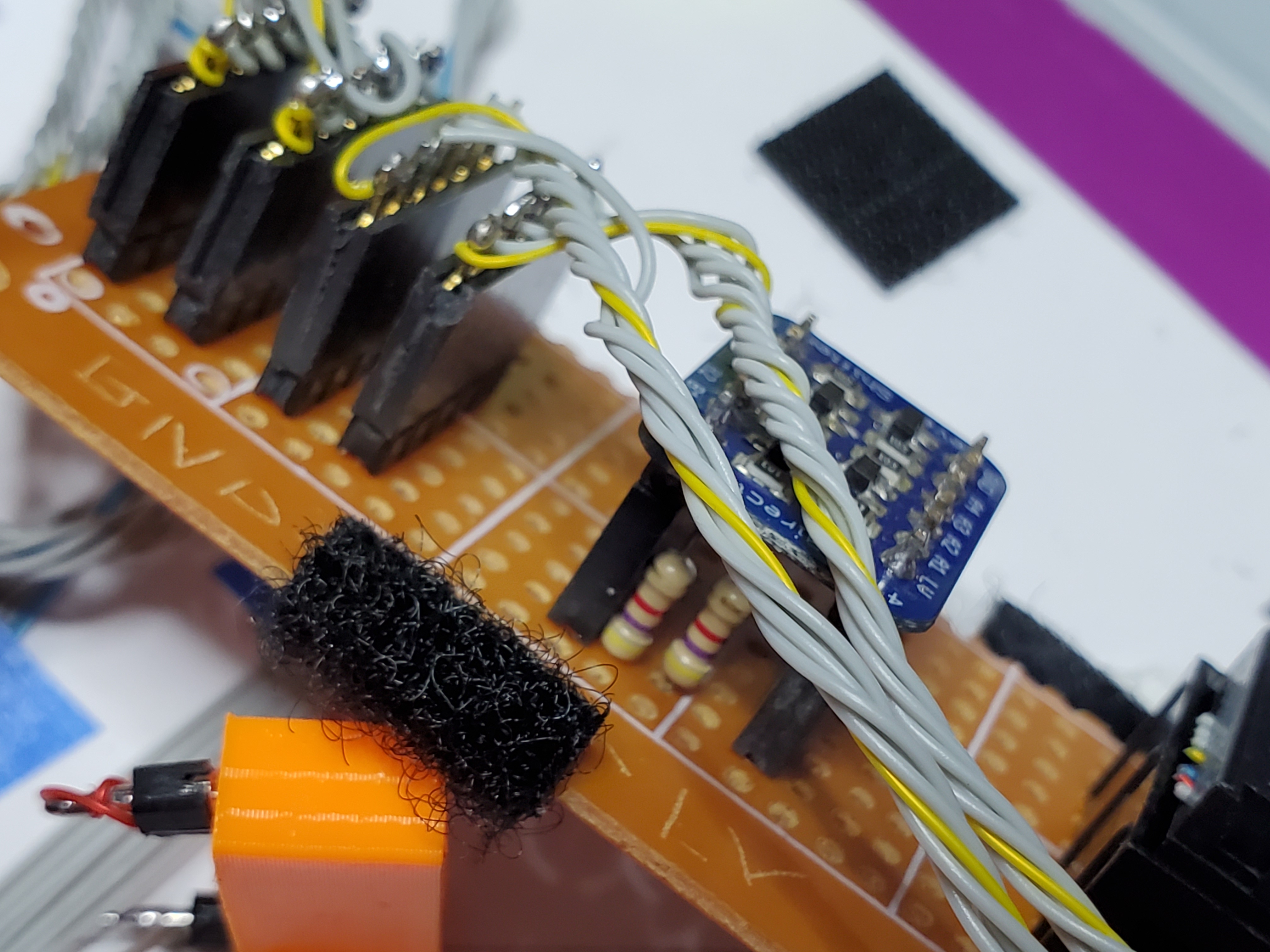
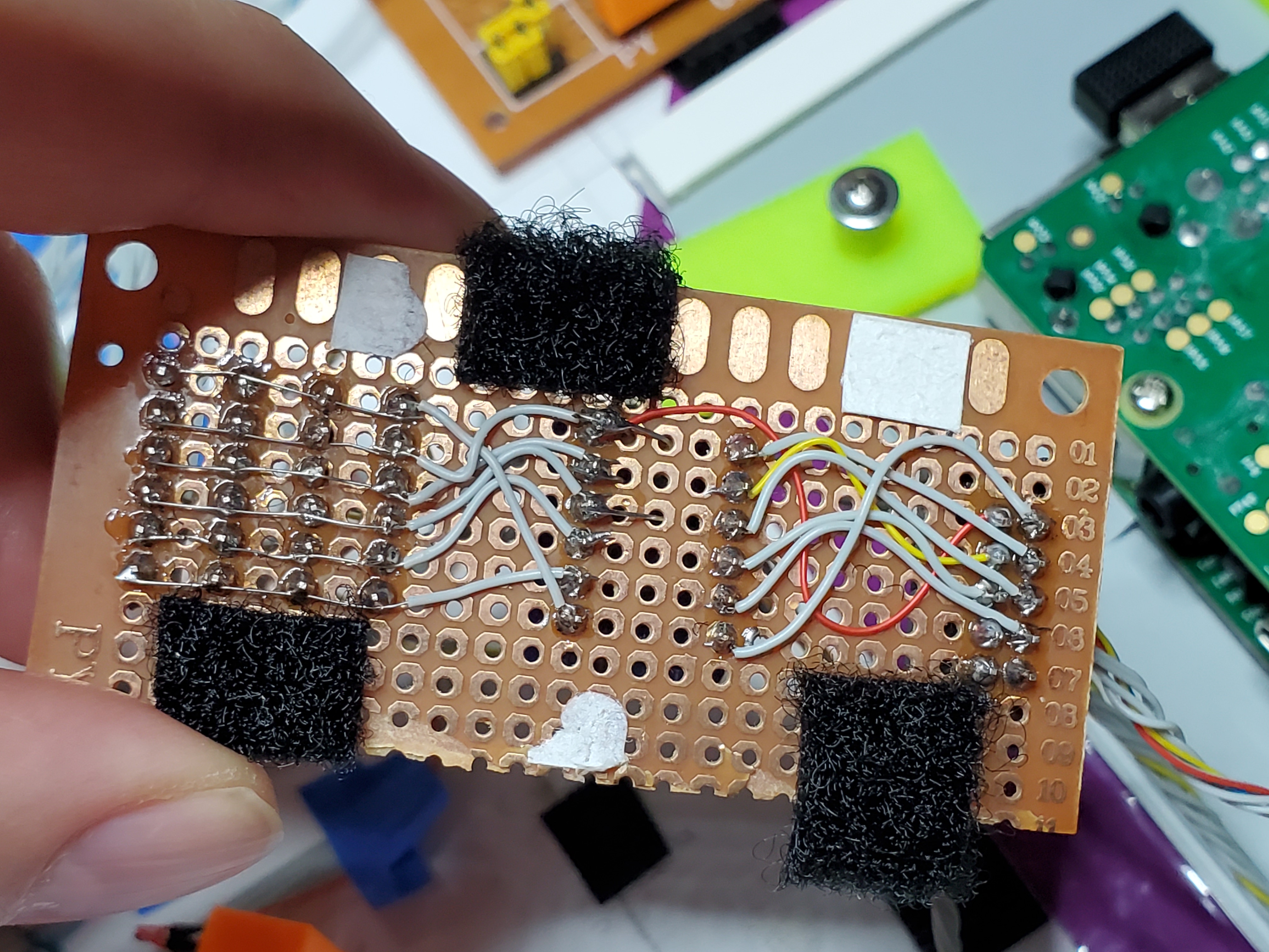
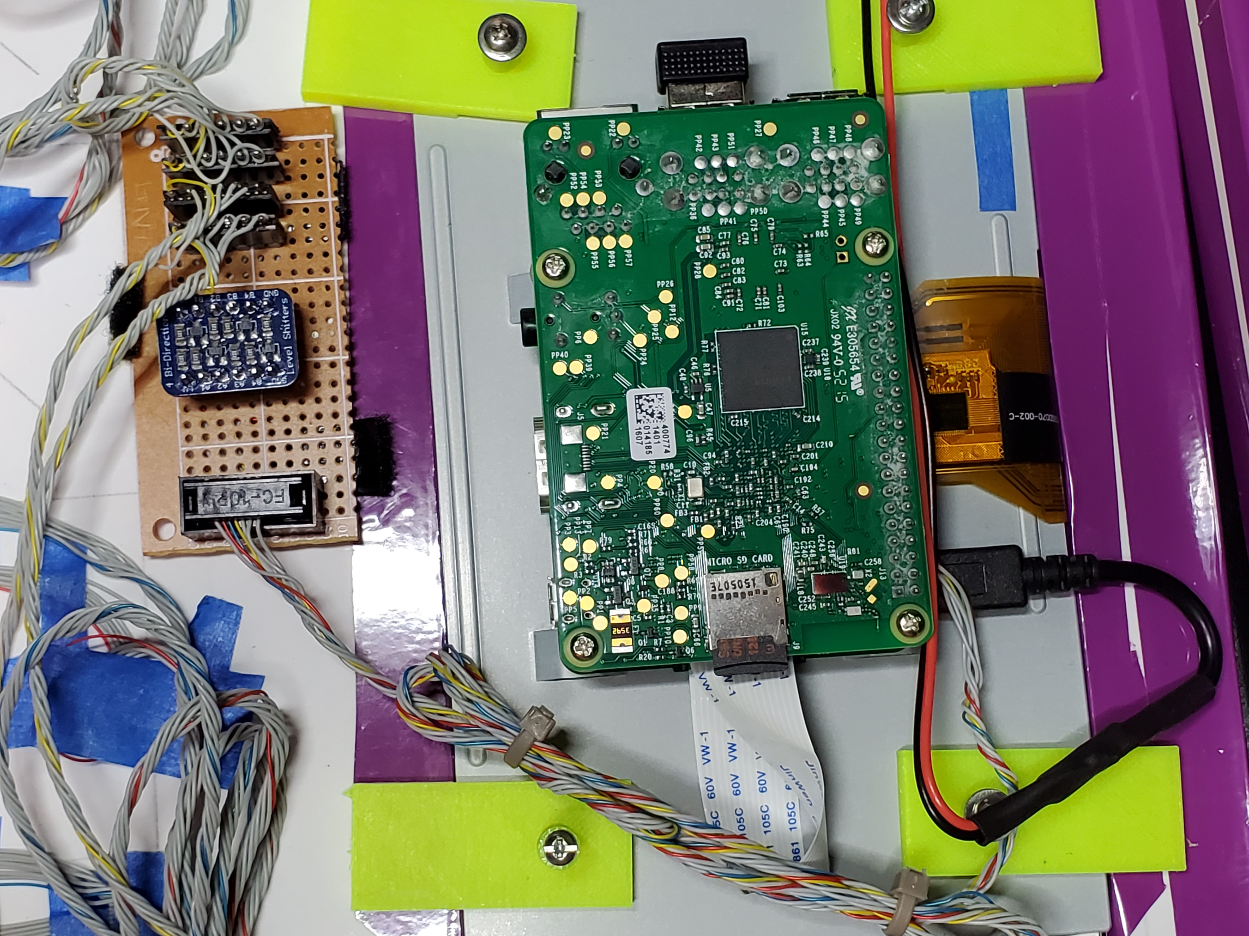
Quick tour of the assembled board. Power comes from the 5v pin of the PI to the i2c bridge board. i2c wires are as well. From there the bridge board, power and i2c lines go to each of the MCP boards. I also have a couple extra wires running from the PI to the bridge then to the MCP boards for future expansion. I was thinking maybe it could be used to reset the MCP chips.
Figure 1: All MCP boards
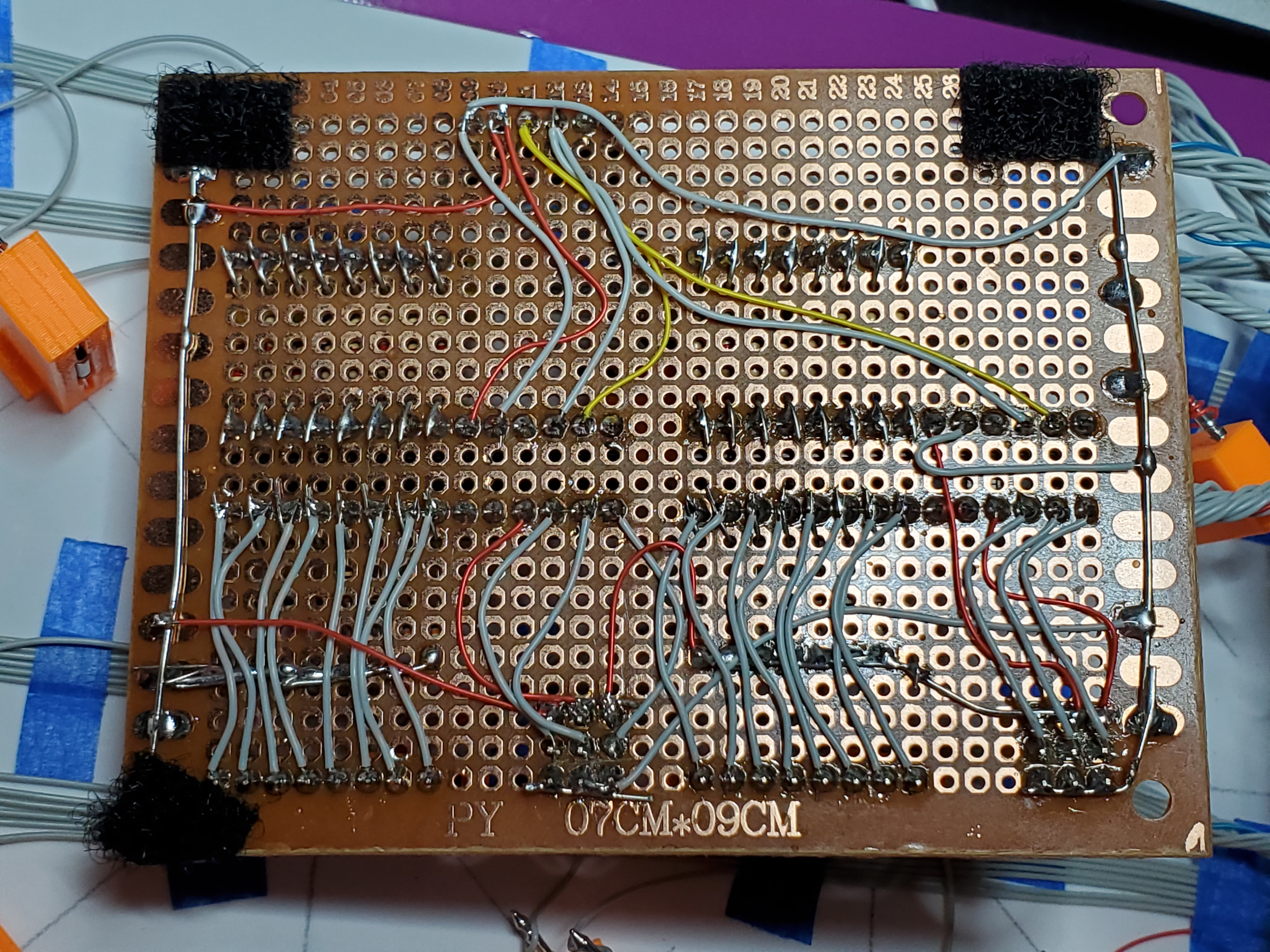
Figure 2: Underside of MCP board
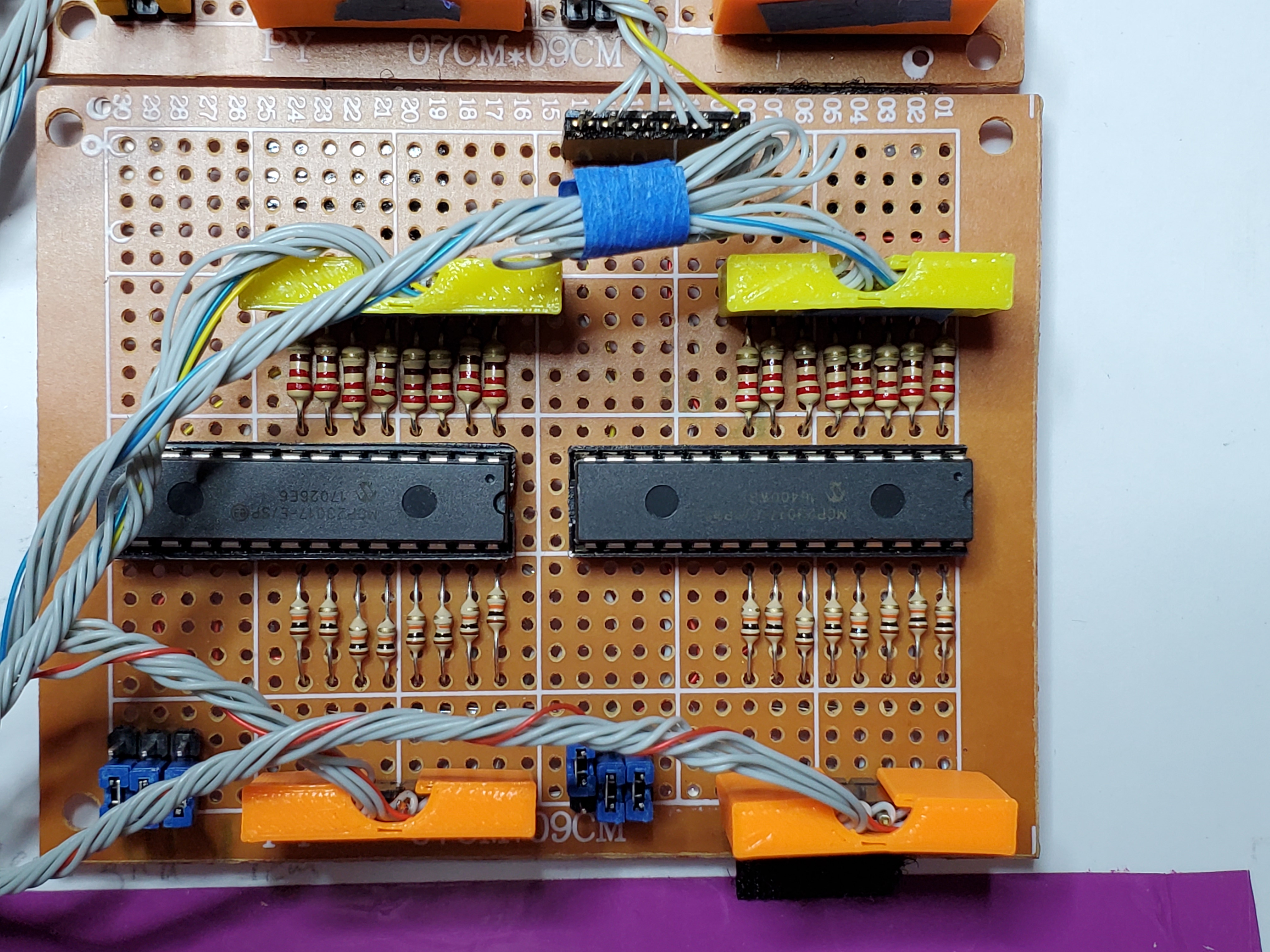
Figure 3: Top of MCP board
Figure 4: Top of i2c bridge board
Figure 5: Side view of i2c board showing resistors for i2c wires
Figure 6: Underside of i2c bridge board
Figure 7: Bridge and PI
